محتوى
A heating furnace burner is the core combustion component of any industrial or commercial furnace — it converts fuel and air into a controlled flame that generates the thermal energy needed to heat metal, glass, ceramics, or process gases to precise target temperatures. Every other aspect of furnace performance — energy efficiency, temperature uniformity, throughput, emissions compliance, and operating cost — is directly determined by burner selection, configuration, and maintenance.
In industrial heating systems, burner performance is not marginal. A poorly selected or poorly maintained furnace burner can waste 15–30% of fuel input as unrecovered heat, push NOx emissions above regulatory limits, and cause temperature non-uniformity that scraps product. Conversely, a properly specified high-efficiency burner can cut fuel consumption by 20–40% compared to older atmospheric designs, paying back its capital cost within 12–24 months in high-utilization operations.
Burner type determines flame shape, heat release rate, emission profile, and compatibility with the furnace application. The major categories used in industrial heating furnaces are:
Recuperative burners incorporate a built-in heat exchanger (recuperator) that preheats incoming combustion air using exhaust flue gases. Preheating air to 400–600 °C can reduce fuel consumption by 25–35% compared to cold-air burners at the same output. They are the most common high-efficiency choice for continuous furnaces operating above 800 °C, such as forging and heat-treatment furnaces.
Regenerative burners work in pairs, alternately firing and exhausting through ceramic heat-storage media (regenerators). Air preheat temperatures can reach 800–1,000 °C, reducing fuel use by up to 50–60% in very high-temperature applications (above 1,100 °C) such as glass melting furnaces and aluminum reverberatory furnaces. The trade-off is higher capital cost and more complex controls.
In radiant tube burners, combustion occurs inside a sealed ceramic or metallic tube, and heat is transferred to the furnace load entirely by radiation. This isolates the combustion atmosphere from the furnace atmosphere — essential for bright annealing, carburizing, and other atmosphere-sensitive heat treatment processes where direct flame contact would oxidize or contaminate the workpiece.
Flat flame burners spread combustion across a wide, disc-shaped flame that hugs the furnace wall or hearth. This design reduces peak flame temperature — the primary driver of thermal NOx formation — while maintaining high heat flux. Modern flat flame burners can achieve NOx emissions below 30 mg/Nm³ at full capacity, meeting increasingly stringent air quality regulations in Europe and North America.
Oxy-fuel burners replace combustion air with pure or enriched oxygen, eliminating the nitrogen ballast that carries away usable heat. Flame temperatures can exceed 2,800 °C, enabling very high heat transfer rates and reducing flue gas volume by up to 75%. They are standard in glass melting, scrap aluminum melting, and certain steel reheating operations where maximum thermal intensity is required.
Matching the burner type to the furnace application is the single most important selection decision. The table below summarizes key parameters for each major burner category.
| Burner Type | Air Preheat Temp. | Fuel Savings vs. Cold Air | Typical Application | Relative Capital Cost |
|---|---|---|---|---|
| Cold Air (Atmospheric) | Ambient | Baseline | Low-temp ovens (<600 °C) | Low |
| Recuperative | 400–600 °C | 25–35% | Forging, heat treatment | Medium |
| Regenerative | 800–1,000 °C | 50–60% | Glass melting, aluminum | High |
| Radiant Tube | Varies | 15–30% | Atmosphere heat treatment | Medium–High |
| Flat Flame / Low-NOx | Ambient–300 °C | 10–20% | Rolling mills, ceramics | Medium |
| Oxy-Fuel | N/A (pure O₂) | 40–60% (fuel only) | Glass, scrap metal melting | Very High |
Understanding the internal anatomy of a furnace burner helps engineers diagnose failures, specify replacements, and evaluate upgrade options.
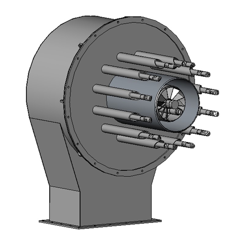
The refractory burner block, or quarl, is the conical or cylindrical ceramic insert through which the flame exits into the furnace chamber. It stabilizes the flame root, protects the metal burner body from radiant heat, and shapes the initial flame geometry. Material selection — high-alumina, silicon carbide, or fused silica — is matched to the operating temperature; blocks for furnaces above 1,200 °C typically require ≥90% Al₂O₃ content.
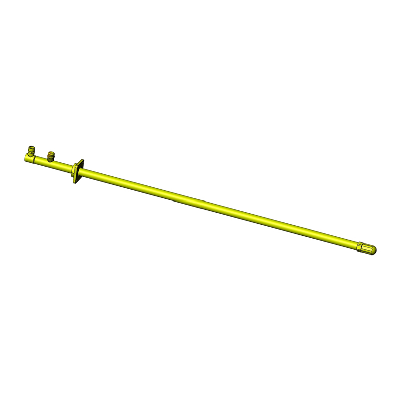
The fuel nozzle controls fuel injection velocity, distribution pattern, and atomization (for liquid fuels). Nozzle geometry determines whether mixing with air is premixed (fuel and air combined before the flame), partially premixed, or diffusion-only (mixing occurs at the flame front). Premixed designs achieve lower NOx and CO emissions but require more careful pressure management to prevent flashback.
The air register controls the flow rate and rotational pattern of combustion air entering the burner. A swirler imparts angular momentum to the air stream, creating a recirculation zone at the flame root that stabilizes combustion, improves fuel-air mixing, and broadens the stable operating range of the burner. Swirl number — a dimensionless parameter — typically ranges from 0.4 to 1.5 in industrial heating burners; higher values produce shorter, wider flames.
Reliable ignition and continuous flame monitoring are safety-critical. Most industrial burners use a high-voltage spark igniter (10,000–15,000 V) for ignition and a UV scanner or ionization rod for flame detection. The flame safeguard controller must detect loss of flame and close the fuel safety shutoff valve within 4 seconds per EN 746-2 and equivalent standards — a requirement that is non-negotiable in safety-certified installations.
The combustion air fan (forced-draft) supplies air at the correct pressure and flow rate across the burner's full firing range. A ratio controller — either mechanical (cross-connected valves) or electronic (mass flow meters with PLC control) — maintains the fuel-to-air ratio within a tight band. Excess air of 5–15% above stoichiometric is typical for natural gas burners; higher excess air wastes fuel by heating nitrogen, while insufficient air causes incomplete combustion, CO formation, and soot.
Heating furnace burners are designed for specific fuels. Switching fuels without re-engineering the burner is a common and costly mistake.
Burner selection requires a structured engineering process. Skipping steps leads to oversized burners that short-cycle, undersized burners that limit throughput, or mismatched designs that create emissions violations.
A burner without effective combustion control cannot maintain temperature uniformity, optimize fuel consumption, or respond safely to process upsets. Modern furnace burner systems use one of three control approaches:
The simplest and cheapest approach. The burner fires at full capacity and shuts off when the setpoint is reached, cycling repeatedly. Suitable only for batch furnaces with slow thermal response where temperature overshoot of ±10–20 °C is acceptable. High cycle count accelerates wear on burner components and safety valves.
The burner operates at either high fire (typically 100% capacity) or low fire (25–40% capacity), switching between the two based on furnace temperature. This reduces cycling frequency and thermal shock compared to on/off control, and is the most common approach in medium-sized industrial furnaces.
Modulating control is the highest-efficiency option, continuously adjusting burner firing rate from minimum to maximum in response to a PID temperature controller. Combined with electronic ratio control (adjusting both gas and air flows in proportion), modulating systems maintain temperature to within ±2–5 °C of setpoint and minimize excess air across the full firing range, optimizing fuel efficiency at all load levels.
Nitrogen oxide (NOx) emissions from heating furnace burners are regulated globally and are tightening. Two technologies now dominate low-emission furnace heating above 1,000 °C:
Air or fuel is introduced in multiple stages, deliberately creating fuel-rich and fuel-lean zones that avoid peak flame temperatures. By keeping local flame temperatures below the thermal NOx threshold of approximately 1,500 °C, staged combustion burners can reduce NOx by 40–60% compared to conventional designs while maintaining the same heat output.
In flameless oxidation mode, fuel and air are injected at high velocity into a furnace chamber already above the auto-ignition temperature of the fuel (~600 °C for natural gas). The high-momentum jets entrain large volumes of hot furnace gases before combustion begins, diluting the reactants and distributing heat release over a much larger volume. This eliminates the visible flame and keeps peak combustion temperatures below 1,300 °C — dramatically reducing NOx to levels as low as 5–15 mg/Nm³. The additional benefit is exceptional temperature uniformity across the furnace load, often within ±5 °C.
The majority of heating furnace burner failures are preventable through systematic maintenance. Unplanned burner outages in continuous furnace operations can cost $10,000–$100,000 per hour in lost production, depending on the industry. A structured maintenance program should include the following intervals:
| Interval | Maintenance Task | Purpose |
|---|---|---|
| Daily | Check flue gas O₂ / CO via analyzer | Verify combustion ratio; catch drift early |
| Weekly | Inspect flame scanner signal strength | Ensure reliable flame detection; prevent nuisance trips |
| Monthly | Clean igniter electrode; check spark gap | Prevent ignition failure; maintain 3–4 mm gap |
| Quarterly | Inspect burner nozzle for scale / blockage | Restore correct fuel distribution and flame shape |
| Annually | Full burner teardown; replace seals and refractory block | Prevent unexpected failure; restore as-new performance |
| Annually | Test and certify safety shutoff valves | Regulatory compliance; prevent gas leak and explosion risk |
Combustion analysis — measuring flue gas O₂, CO, CO₂, and temperature — is the single most cost-effective diagnostic tool available. A flue gas O₂ reading of more than 3–5% above the target setpoint on a natural gas burner typically indicates air infiltration, ratio controller drift, or a blocked fuel nozzle, each of which can be corrected in minutes if caught early but may require full burner replacement if left unaddressed for weeks.
Knowing the signature of each failure mode allows faster root-cause identification and reduces mean time to repair.
Decarbonization targets in steel, aluminum, glass, and ceramics manufacturing are driving rapid development of next-generation heating furnace burners. Three directions are receiving the most investment:
Many burner manufacturers now offer "hydrogen-ready" designs capable of firing natural gas / hydrogen blends up to 30% H₂ by volume without hardware modification. Above 30%, flashback protection measures — such as flame arrestors, reduced nozzle diameter, and increased air-side pressure drop — become necessary. Blending at 20% H₂ reduces CO₂ emissions by approximately 7% per unit of heat delivered, reflecting hydrogen's lower carbon content and higher flame temperature.
Several manufacturers have demonstrated stable 100% hydrogen combustion in industrial furnace burners at pilot scale. Key engineering challenges include managing the 2.4× faster laminar flame speed of hydrogen (compared to methane) and controlling elevated water vapor levels in the furnace atmosphere, which can affect surface quality in steel reheating applications. Commercial deployment is accelerating for 2025–2030.
Hybrid furnaces combining gas burners for bulk heating with electric resistance elements for precise final-temperature hold are emerging as a practical near-term decarbonization path. The burners handle the high heat-input phase efficiently while the electric system eliminates combustion emissions during the sensitive hold phase. This approach can reduce total combustion-related CO₂ emissions by 30–50% without the supply-chain risk of a full switch to hydrogen or full electrification.


 الشركات المصنعة لمعدات الاحتراق والأنظمة الحرارية عالية الأداء (بنظامي OEM وODM)
 English
 русский
 Français
 Español
 عربى
عربى